PRJ_04 · OSPF
Multi-Area OSPFv2/3
The other day I was casually poking around the 350-401 ENCOR official exam topics and noticed 3.2b: “configure simple OSPFv2/v3 environments, including multiple normal areas, summarization, and filtering (neighbor adjacency, point-to-point, and broadcast network types, and passive interface)” and I was like BETSY, COME GET THE COWS, I totally know how to do like half of that and the other half I can figure out. Let’s get started.
Provisional Table of Contents:
- Lab 1: Multi-Area OSPF(v2/3) Default State of Mind Include broadcast/point-to-point network types
- Lab 2: Summarization & Filtering Summarization at the ABRs and both “area filter lists” which operate on your LSDB and “distribute-lists” which operate on the local router’s RIB.
- Lab 3: Stub Time Work in progress — ETA week of 9/21/26
I’m probably going to say this a thousand times, in a thousand different ways: this is not intended to be exhaustive nor authoritative. I’m actively working towards my CCNP (haven’t married a path yet), and presenting this helps me better understand it. Also…I just haven’t encountered a ton of blogs like this. One could say there’s a dearth. Like, the opposite of a plethora. There’s an anti-plethora of (haunted?) training material geared towards me, the Post-CCNA.

Topology & Addressing Note: In order to make show commands a little easier to decipher, IPv4 and IPv6 addresses follow the schema below unless otherwise indicated:
- Every address begins with
10.for IPv4 and2001:c0defor IPv6. -
The first octet/hextet after that is the area (e.g.
10.2.x.x,2001:c0de:2:x:x). -
The next octet/hextet represents the router #s belonging to the interfaces being connected. Ergo, the
links between R6 and R8 (which are in Area 2) are
10.2.68.1/30&2001:c0de:2:68::1/64on the R6 interface and10.2.68.2/30&2001:c0de:2:68::2/64on the R8 interface. -
Loopbacks for IPv4/6 just repeat the router # over those same octets/hextets (but with IPv6 swapping
2001:c0defor2001:dead). Therefore, the loopback0 for R6 is6.6.6.6/32&2001:dead:6:6::6/128. -
Infrastructure routes throughout are configured as OSPF network point-to-point, whereas endpoints are
attached to OSPF broadcast /24s for IPv4 and the /64 “boo” network for IPv6
 .
.
Lab 1: Multi-Area OSPF Default State of Mind
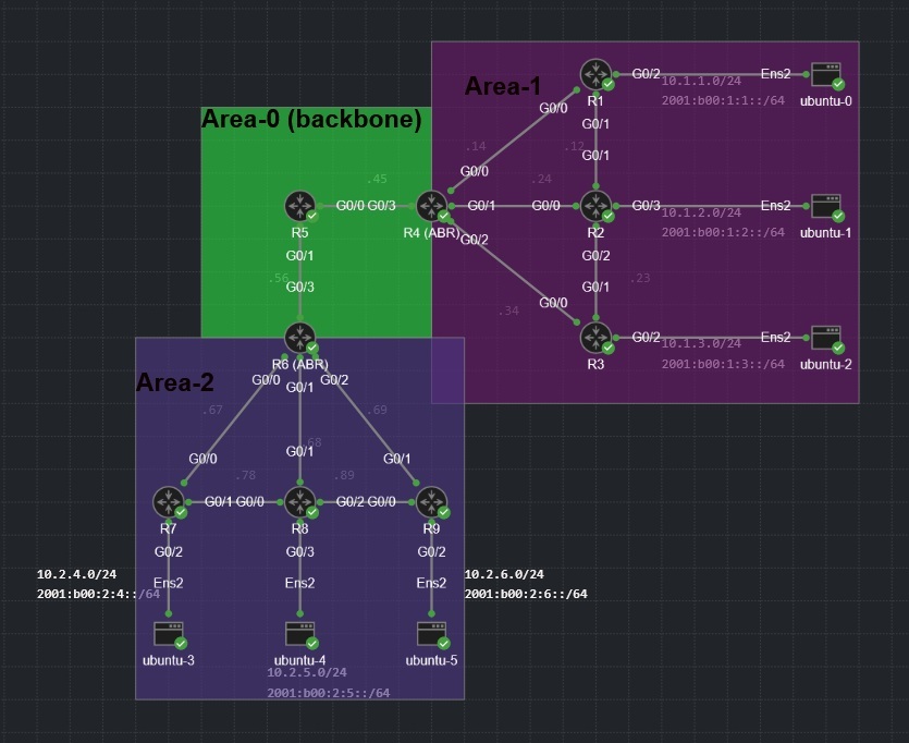
We’re going to do several interesting things with our default configuration, and they represent a significant departure from how I configured OSPFv3 in my previous BGP labs. For the uninitiated, here is how I configured the (working!) general OSPFv3 configuration for anything that didn’t have a passive-interface attached to it:
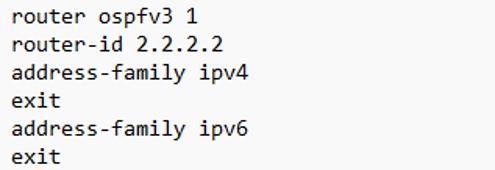
Then in place of the “network” command, we’d affix ipv4 ospf 1 area 0 and
ipv6 ospf 1 area 0 to the interfaces whose addresses were previously getting network’d.
This is the method described in RFC 58381 (“Unified OSPFv3”, “OSPFv3 AF”, “OSPFv3 As Fuck”), and it’s a great way to implement dual-stack because IPv4 and IPv6 still have their own process and LSDB but the configuration is far simpler and easier to troubleshoot. The downside is: my ENCOR specifically refers to OSPFv2/3 firstly, secondly since OSPFv3 uses IPv6 for transport, you can’t run it on an IPv4 only interface. I want this demonstration to be inclusive, so I’m going to run the “old school” IPv6-only version of OSPFv3 from RFC 53402, then run OSPFv2 for muh IPv4.
Confessor’s Note: I don’t actually give a good goddamn about being “inclusive” and that wouldn’t make sense in context regardless. The truth is I was TRICKED into believing the RFC 5340 way was the “correct way” and the RFC 5838 way was for greenhorns. In sales, they use “ABC” as in Always Be Closing. In network engineering, one ought to use “ABCYEA”, as in Always Be Checking Your Epistemic Authorities.
Anyway, where were we?
Ah yes, we were building a network.
There are a few key principles to keep in mind when working with multi-area OSPF. Each area must connect to “the backbone” or Area 0, and your ABRs (area border-routers) will have at least one interface in Area 0, with its internal interfaces assigned to the area its hosting. If that sounds like gibberish here’s what that looks like in practice:
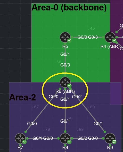
GigabitEthernet0/0 – 0/2 will be assigned to Area 2 on both IPv4 and IPv6, while the GigabitEthernet0/3 interface is assigned to Area 0.
Another important aspect to take note of is most of these links are point-to-point /30s. By default, OSPF assumes all Ethernet interfaces are broadcast interfaces. For me personally, this has never caused any functionality issues, but it does cause unnecessary DR/BDR elections (which chew up overhead) and it causes incorrect LSA-types to go out (LSA type 1s are for point-to-point router connections and type 2s are supposed to come from DRs connecting to a transit network3). So that gets fixed starting TODAY.
The long and short of this whole thing is our general OSPF configuration is extremely bare-bones (especially since this implementation doesn’t use address-families). Most of the configuration lives on the interfaces. The general OSPF config for R1 is just this:
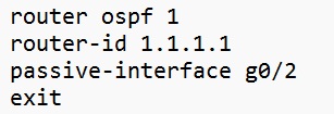
That g0/2 interface is connected to an endpoint on the 10.1.1.0/24 & 2001:b00:1:1::/64 networks. The
internal routers (R1-R3 and R7-R9) each host broadcast /24 (IPv4) and /64 (IPv6) networks. These will get
passive-interface’d since endpoints don’t need LSAs, but we will affix
ip ospf 1 area 1 and ipv6 ospf 1 area 1 to the interface configuration so those
networks also get advertised. There’s no need to specify a network type — since it’s an
Ethernet interface OSPF will assume it.
Here is the configuration for everyone in our topology:
Click router or server for default config commands
If you perused the previous BGP section, you will notice that at no point is the command
ospfv3 used anywhere. I’ll admit I was confused and felt like this was just a
different way of implementing OG OSPF. But if you run any of the ospfv3 show commands, you’ll see
it’s there, in fact it’s where our IPv6 OSPF configuration lives:
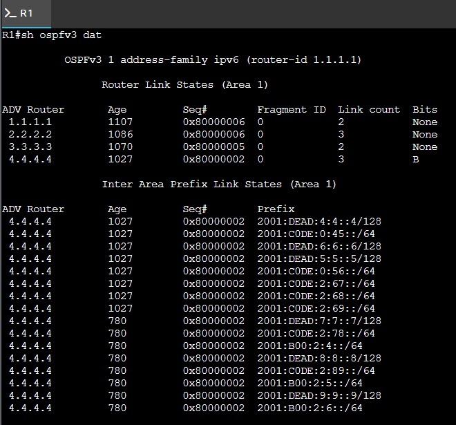
As mentioned at the top, we have IPv4 riding OSPFv2 and IPv6 riding on OSPFv3. You will find the line
ipv6 router ospf 1 in my startup-config on all these routers, but I didn’t put it
there, it auto-populated when I put ipv6 ospf 1 area x onto an interface. If you look
closely, you will also see in the output of show ospfv3 database shows a router-id of
1.1.1.1. I wasn’t sure if this was assigned that way because of my loopback, so I changed the
loopback0 of R1 to 100.100.100.100/32:
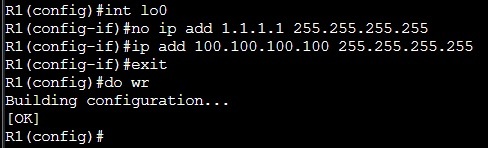
And to make sure I’m not screenshooting old config, gonna run a
clear ospfv3 process:

Did that change my ospfv3 router-id?

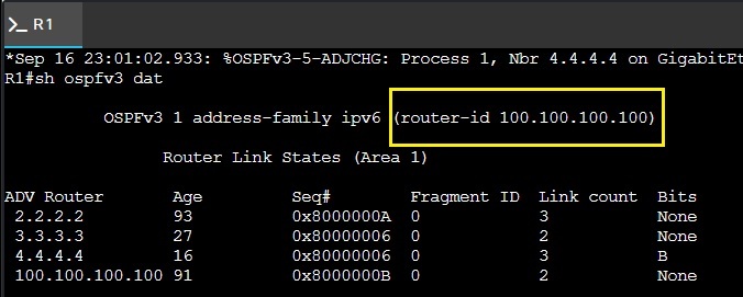
Okay FINE. So ospfv3 did scoop up my IPv4 loopback0 and assign it as its router-id since I didn’t explicitly assign one. That’s fine. I’m not mad. Had it occurred to me before typing the previous paragraph, I would have assigned that ID. Best practice would involve including that line in your configuration. Don’t be like the dude who runs network-foibles. Assign a router ID, like, intentionally.
Alright, all of this notwithstanding, how do I know this configuration even worked? Probably the fastest way to check your configuration is through the ABRs R4 and R6. They both have four OSPF neighbors (eight if you count both processes), and if any of them are missing we know we have an issue. Let’s look there first:
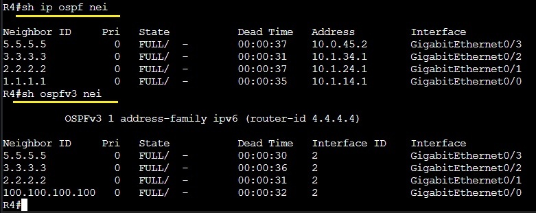
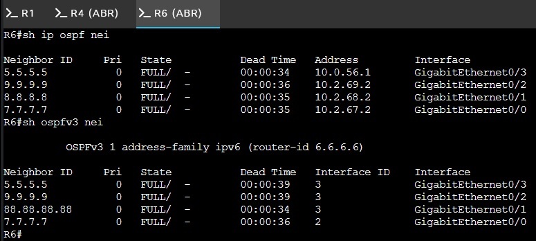
Here we have both neighbor commands (from OSPFv2 and OSPFv3) and all neighborships are accounted for on both protocols.
Let’s check routing tables next. I’m going to pick on R8:
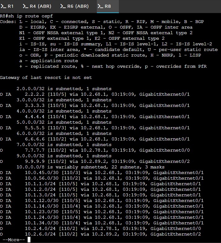
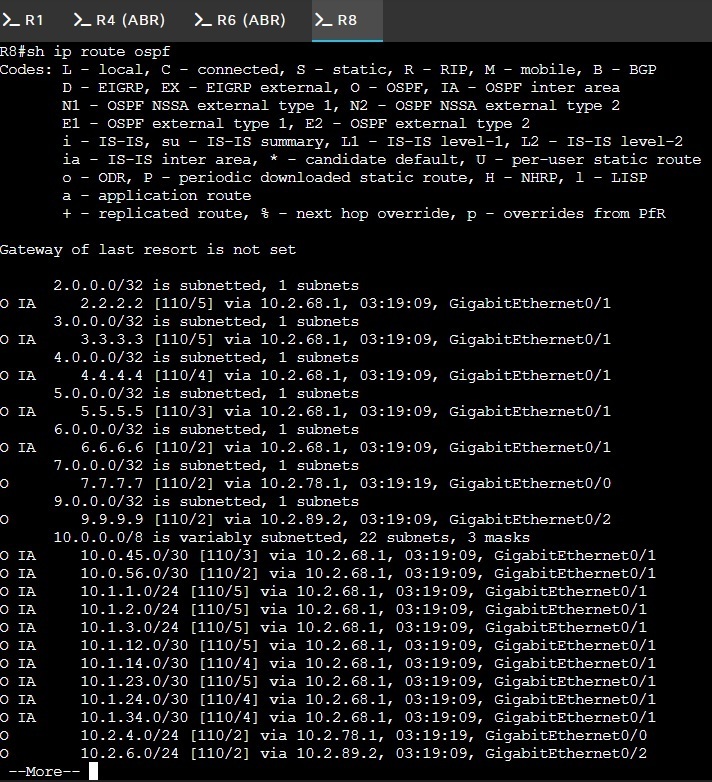
You can see all the IPv4 loopbacks up top (except 100.100.100.100, which you will find on the very bottom). What’s neat about this addressing schema is you can just look at the network diagram and compare it to the routing-table to see what (if anything) is missing. My inter-area (IA) routes are everything from Area 1 and Area 0. The only networks that appear to be missing are the 10.2.5.0/24 network and the 10.2.68.0/30 network (I also don’t see R8’s loopback). Oh wait…
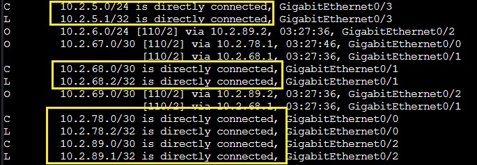
Ah see, the problem with appending “ospf” to the show ip route command is that’s going to exclude any network that is directly connected to that router. Whoops.
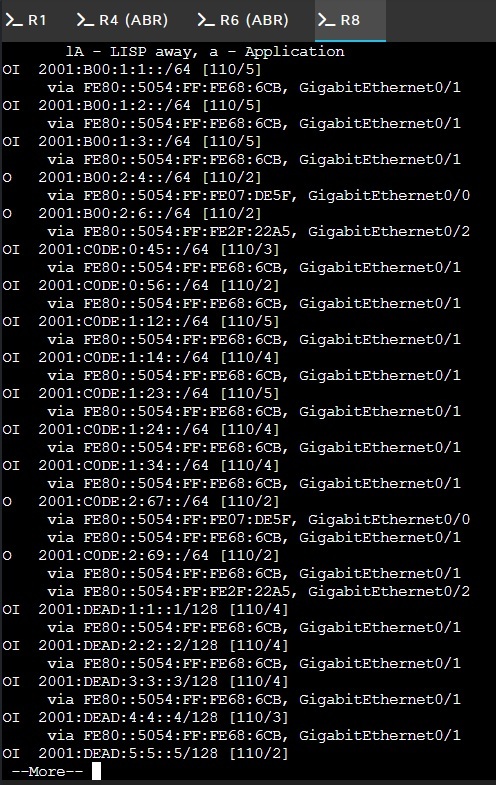
The show ipv6 route command has longer output but the idea is still the same:
But the ultimate test is reachability. I should be able to ping any router from any other router, in either layer-3 protocol.
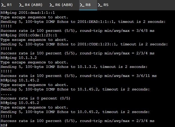
If you look closely, you will see a failed ping in there. That happened because I got the area wrong (that interface is in Area 0, so that address wouldn’t exist).
We have full connectivity, all of our neighbors seem to be there and acting all neighborly and what not. I think we’ve reached our Default State (of mind). But if feels like there’s something important, indeed vital, that we’re missing…
…
…oh yeah.
Why in the hell do we even need areas?
In a single, flat OSPF area, every router carries a full copy of the link-state database (LSDB) for the entire domain. Any time any router receives new information about a topology change, it must rerun the SPF (Dijkstra) algorithm, create a new SPF tree, and update the routing table. SPF is CPU-intensive and takes longer to calculate as the area grows. With multi-area OSPF, you can divide your AS hierarchically, with more expensive operation like recalculating the database kept within a defined area4.
I also like that you’re taking one large failure domain and breaking it up into smaller, baby failure domains.
Lab 2: Summarization & Filtering
Now time for the embarrassing part: laying bare the fact that I made no effort to preserve my I pee vee four. Naturally, in a real-world scenario, you would want to design your areas so that everything can be addressed within a particular bit-boundary. So for instance I could’ve used 10.0.0.0/24 and broken that into /30s for my Area 1 infra, which would make everything in Area 1 summarizable as 10.0.0.0/22 (covers 10.0.0/24 – 10.0.3.0/24). Then I could use 10.0.7.0/24 for /30s on the Area 2 infra, and that area then summarizes to 10.0.4.0/22. This is how you would modularize the addressing and area assignment in say a Campus LAN (at least in the Old Days).
Now that you know that I can do it, I promised there would be no math so I stuck my area assignment in that 2nd octet to make it easy for everyone involved. All I’m doing is demonstrating how this works: we’re going to have the Area 1 ABR (R4) grab everything in 10.1.0.0/16 and our Area 2 ABR (R6) grab everything in 10.2.0.0/16. On the IPv6 side, we’re doing things a little goofy and just summarizing our infra with 2001:c0de:1::/48 in Area 1 and 2001:c0de:2::/48 for Area 2. And with that, I’ve officially burned more addresses for this dumb, tiny network than there are atoms in the Known Universe. At least I think I did. Are there more than 2.42 x 1024 atoms in the Known Universe? Sound off in the comments.
Here’s what the summaries I’m putting on R4 and R6 look like:
Click R4 or R6 for summarization commands
Now let’s take a peek at R5’s routing table:
Here it was before:
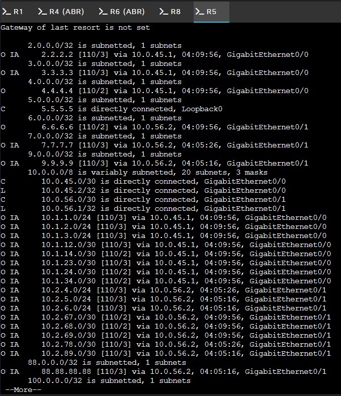
And here it is now:
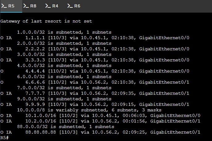
And here’s the IPv6 side:
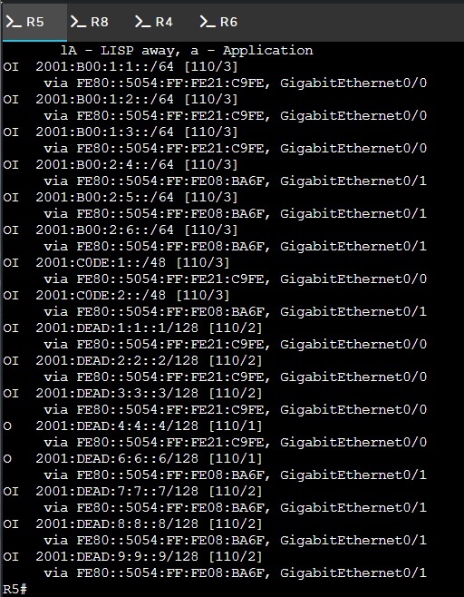
Originally I was using a much simpler topology for this section, but I scrapped that and used this one instead because I wanted to adequately demonstrate what an important tool this is. Even a network this simple has routing tables that are pretty damn unwieldy, and SPF is being run across it all every time there’s the smallest change.
I also wanted to show off another cool trick:
# R4 Loopback filter
ip prefix-list HIDE-AREA1-LOOPBACKS seq 10 deny 1.1.1.1/32
ip prefix-list HIDE-AREA1-LOOPBACKS seq 20 deny 2.2.2.2/32
ip prefix-list HIDE-AREA1-LOOPBACKS seq 30 deny 3.3.3.3/32
ip prefix-list HIDE-AREA1-LOOPBACKS seq 40 permit 0.0.0.0/0 le 32
router ospf 1
area 1 filter-list HIDE-AREA1-LOOPBACKS out
exit
do wr
…
And with that we accomplish this:
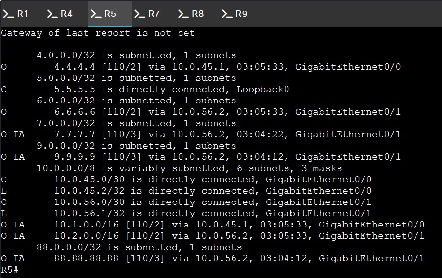
SOON THE R5 ROUTING TABLE WILL BE REDUCED TO NOTHING MUA HAHAH!!!
So this is called an “OSPF Area Filter” in the nomenclature and you can apply these to ABRs
to prevent specified routes/networks from being advertised outside the area via the ABRs type-3 LSAs
(or OSPF inter-area link-state advertisements for the acronym-weary). These types of filters are
triggered with the filter-list invocation within your OSPF configuration, which is
important to point a big, fat arrow on because there’s also a distribute-list
command that acts similarly except it only applies to your local configuration (more on that
here5). Placing a distribute-list on an ABR won’t affect its LSAs or anyone else’s, but you can
use filter-list for any networks that don’t need to leave area.
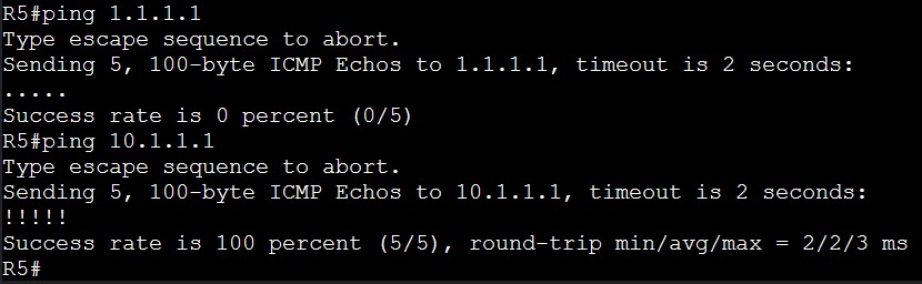
As it effects connectivity across my network, I can’t reach R1’s loopback from R5, but I can reach the 10.1.1.1/24 broadcast network its hosting:
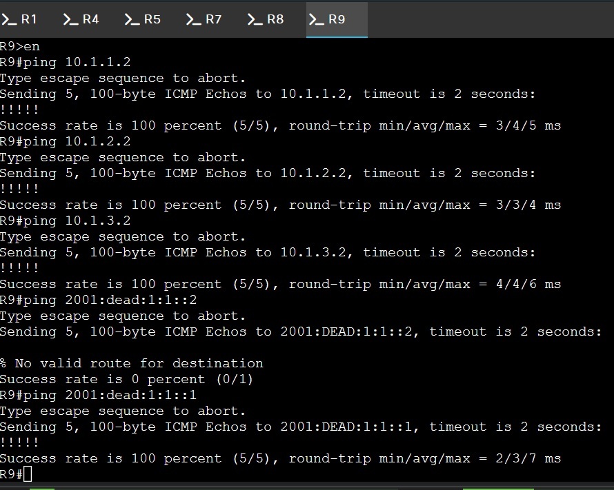
Likewise, summarization and filtering hasn’t affected connectivity from Area 2 of my Area 1 endpoints:
Lab 3: Stub Time
…to be continued…work in progress…ETA week of 9/21/26
Footnotes
- RFC 5838 — Support of Address Families in OSPFv3 rfc-editor.org ↩
- RFC 5340 — OSPF for IPv6 rfc-editor.org ↩
- NetworkLessons — OSPF LSA Types Explained networklessons.com ↩
- University of Tartu — Multi-Area OSPF courses.cs.ut.ee ↩
- Cisco Community — OSPF Filtering community.cisco.com ↩