PRJ_03 · BGP
An Exploration of BGP
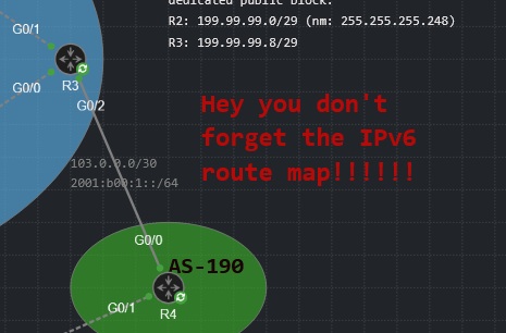
My intention here is to document my own journey exploring everyone’s favorite (only) exterior gateway protocol, Border Gateway Protocol, or BGP to its friends. This was my first time working with this protocol, so I explored some introductory videos and poked my head around Cisco’s documentation for it and the relevant RFCs. For this section, I had 3 main goals:
- Lab 1: implement a basic proof-of-concept BGP lab that includes route-sharing without leaking infrastructure routes (IPv4 only).
- Lab 2: implement the same, but with a more modern IGP (OSPFv3) and with dual-stack IPv4 and IPv6.
- Lab 3: create a more realistic deployment that leverages the BGP Best Path algorithm to implement a policy-change. The goal here is to perform traffic manipulation where users in AS-100 take a longer AS-path to reach a specific network while keeping a default shorter AS-path for other traffic.
There are a number of different websites that go into great detail explaining the role of BGP in networks, the BGP Best Path algorithm and its categories and order of attributes, etcetera. What I had more difficulty locating were sufficient examples of straightforward deployments, the configuration commands to run them, and how to verify that everything is working correctly. This isn’t intended as an exhaustive or authoritative treatment, but rather as an instantiation of a simple network engineer dipping his delicate toe into foreign waters. Let’s get started.
Platform note: The images below are screenshots from my deployment of Cisco Modeling Labs (version 2.8). In this section I’m using exclusively Cisco IOSv routers (VIOS Version 15.9(3)) and Ubuntu Cloud Init endpoints.
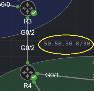
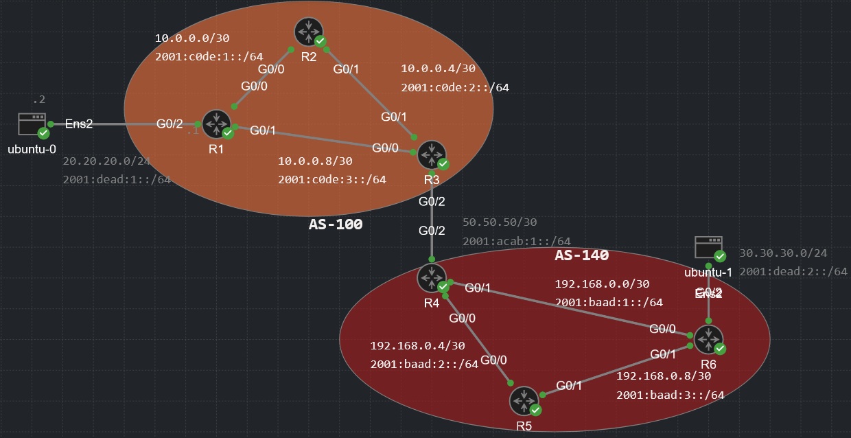
Topology note: Network addresses are used throughout these labs. On /30 addresses, the first assignable address is always assigned to the leftmost interface on the topology. If a connection between devices is stacked vertically (no leftmost), the upmost interface is assigned the first assignable address.
So for instance, for the 50.50.50.0/30 network pictured below, R3’s G0/2 interface is assigned 50.50.50.1 and R4’s G0/2 interface is assigned 50.50.50.2:
Lab 1: Proof of Concept
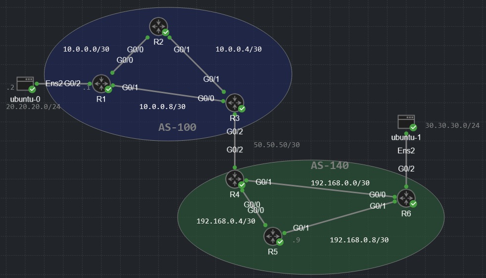
You can strap two routers together and create an eBGP-peering with like 4 commands. Not super interesting. From a pedagogical standpoint, this topology has more to offer: you can pretty much see the basic configuration that’s been placed on these routers, but within each autonomous system (AS-100 and AS-140), each router plays a different role and will have a meaningfully different BGP configuration.
If you look closely, R1 is attached to a public network of 20.20.20.0/24 on its GigabitEthernetG0/2 interface (its counterpart R6 has a public network of 30.30.30.0/24 on the same interface). The goal of this lab is we want each AS to advertise its own public route to the neighboring AS via BGP, without its infrastructure routes being leaked/advertised alongside. I want to be able to ping that server at 30.30.30.2 from AS-100, and I want to be able to ping 20.20.20.2 from AS-140 as well.
To underscore the simplicity of this lab configuration, click a router below for its base (non-BGP) configuration commands:
Click router or server for base config commands
BGP Configuration
A basic BGP configuration only has a few components. You need to establish a full-mesh peering with all
internal BGP routers (excepting the use of “route reflectors” and “BGP
Confederations”). These internal peerings are called iBGP peerings, and both routers/peers must have
issued the command neighbor x.x.x.x remote-as xxx. If you’re using loopbacks instead of
physical interface addresses for these peerings, you will also need to issue the command
neighbor x.x.x.x update-source loopback0. Thus, R2’s BGP configuration looks like this:
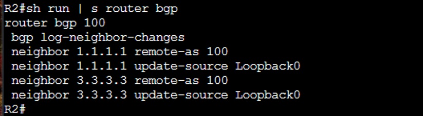
(note: bgp log-neighbor-changes is added automatically to your BGP configuration on this
version of IOSv software)
These were the actual commands that were run on this router:
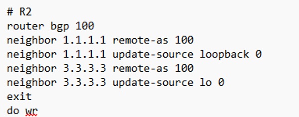
After entering router bgp you need to enter the Autonomous System number (here, 100). All iBGP
peerings/neighbor configurations will reference this same AS number, such as
neighbor 10.0.0.10 remote-as 100 or neighbor 3.3.3.3 remote-as 100.
R1’s configuration will be quite similar, except R1 is hosting the public route we want to advertise
to different ASes. As such, its configuration includes a network command (note the syntax:
network x.x.x.x MASK x.x.x.x):
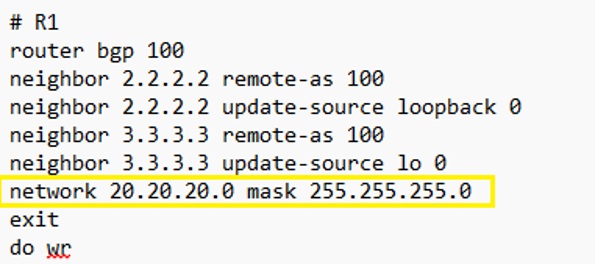
Neteng’s note:
you will find implementations that use the BGP redistribute command, as in
redistribute ospf 1. It does exactly what it sounds like — your infrastructure routes as
well as any routes you’re trying to advertise will be fed into BGP. There are all kinds of environments
where this makes sense, but not here: I’d have to use a route advertisement filter to claw back my
infra routes from AS-140 (at least as far as I know!), which is a dumb way to do a supposedly simple
proof-of-concept lab when the network command is JUST SITTING THERE, waiting to be issued by the router that
is actually sourcing your advertised route (hint).
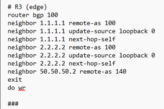
Finally, R3 has its own special command because it’s an edge router. It has an eBGP (external BGP)
peer! Only problem: its BGP next-hop is 50.50.50.2 (R4’s G0/2 interface), which is not in the routing
table for any of AS-100’s internal routers (and it never will be!). So on edge routers you will usually
deploy the command neighbor x.x.x.x next-hop-self for all of R3’s iBGP peers. Thus
R3’s configuration commands look like this:
Click a router below for that device’s full BGP configuration commands (copyable):
Click router for BGP config commands
Verification/Troubleshooting
The next lab has some more ‘meat on the bone’ for this section, but here I’ll cover some handy show-commands to verify your BGP configuration has taken.
As good a place as any to begin is the show ip bgp summary command, which for similar
architecture will produce an output similar to this:
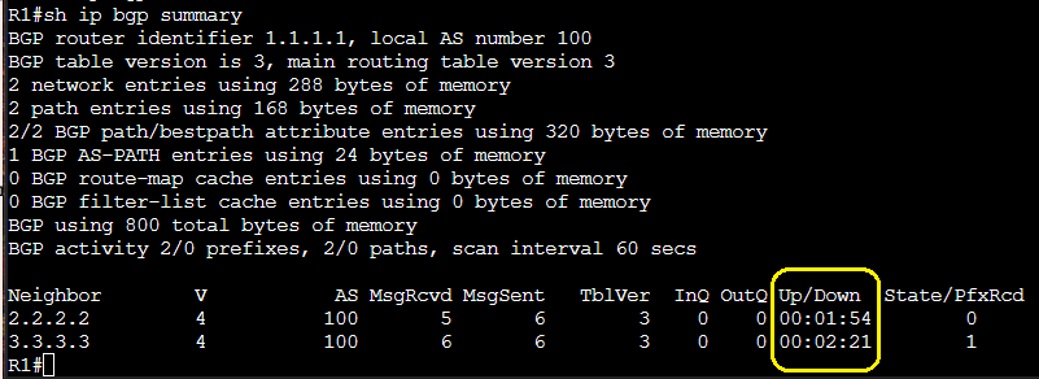
(if the emboxed part of the output above doesn’t show a time count, ya done fucked up somewhere)
Oftentimes if BGP is successfully installed but not working the way you want it to, some clues as to
what’s going on can be found in the local BGP table for that router, which you can view with the
show ip bgp command:
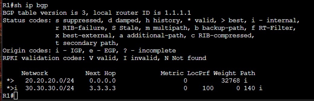
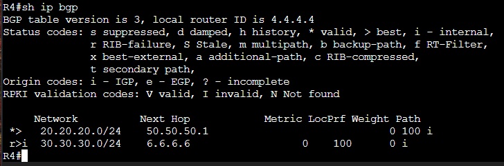
The next-hop for the 20.20.20.0/24 network shows as “0.0.0.0” in this instance because
we’re directly connected to that network. For the 30.30.30.0/24 network in AS-140, we’re given
a next-hop of 3.3.3.3 (the loopback for R3). If you need more detailed info about a particular route, you
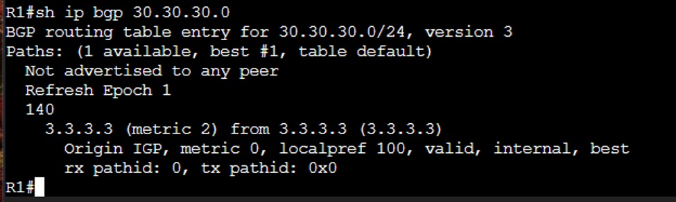
can append the network address to the show ip bgp command (there isn’t much to see in this
context):
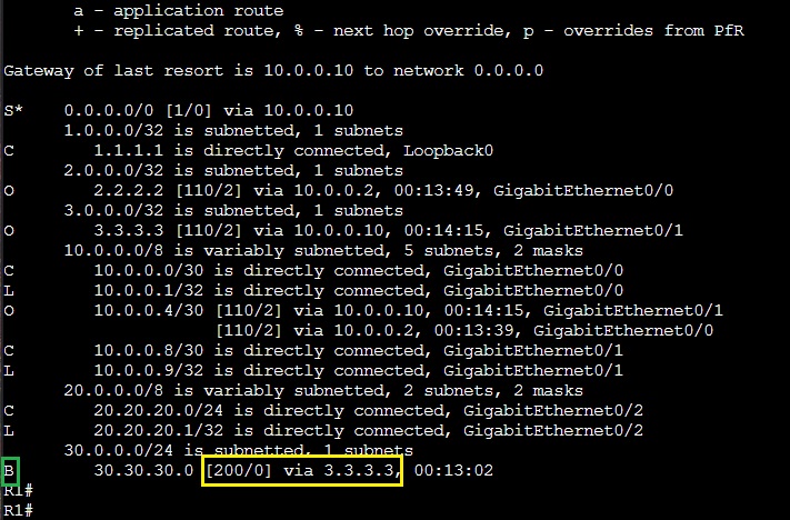
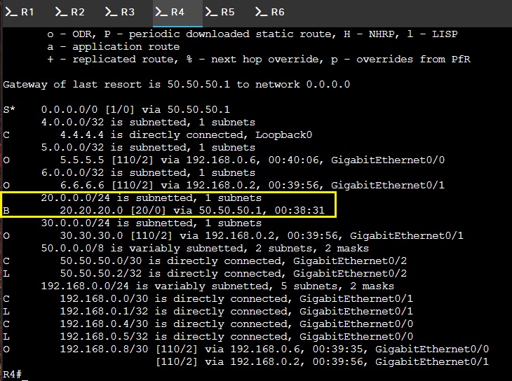
You also have a routing table, which I’m told is important to take a peak at from time to time. Everything I’m looking for is here: my 30.30.30.0/24 network has a “B” for BGP and the 200 ‘cost’ you’d expect to see, also none of AS-140’s infra routes are present, so no “leaks” as it were:
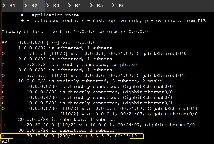
Some other assorted confirmation screenshots for posterity:

Lab 2: BGP with IPv6 and OSPFv3
So there’s a juvenile inside joke here I’m about to spoil, which is I called my IPv6 infra
routes 2001:baad: for AS-100 and 2001:c0de: for AS-140, so that way if I
screwed this up, my IPv6 routing table would print a bunch of routes like this:
2001:baad:1::/64
2001:baad:2::/64
2001:baad:3::/64
2001:c0de:1::/64
2001:c0de:2::/64
2001:c0de:3::/64
Your infra routes are not supposed to leave your AS, so if your routing table says “baad c0de” you did indeed screw up and write bad c0de and should feel bad.
With that out of the way, adding IPv6 and OSPFv3 doesn’t complicate things too terribly, but it is going to change the way we configure BGP and OSPF.
Beginning with OSPF(v3), this version doesn’t use the “network” command. Instead, you
basically just assign a process number (e.g. router ospfv3 1), assign a router-ID if you
like, then define whether you’re using IPv4, IPv6, or both, and whether you’re using any
passive interfaces.
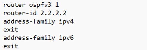
Here is a bare-bones version of a basic OSPFv3 configuration in command form (minus the interface configurations):
Base Configuration
So, what happened to the network command? Instead of manually typing out the network addresses you want
that router to share, you just affix ospfv3 1 ipv4 area 0 (assuming your OSPF process ID is 1
and your area is 0) to the interface configuration attached to any IPv4 network you want OSPF to share. For
IPv6 networks, it’s just ospfv3 1 ipv6 area 0.
With the addition of IPv6 addressing our base-configuration is a skosh longer but should still be fairly legible:
Click router or server for base config commands
BGP Configuration
Moving forward I’m always going to incorporate IPv6. As such, our new BGP configurations are going to
include address-family as there are general config commands that apply to both IPv4/6 as well
as commands specific to each. This is what the new configuration looks like for R1:
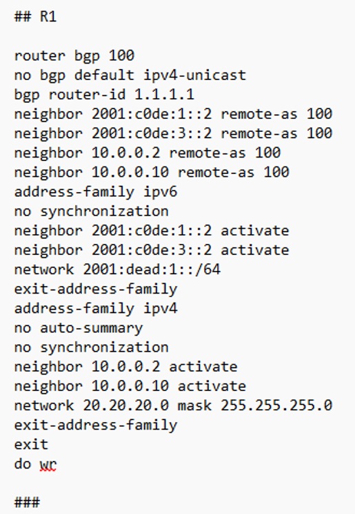
Note: I used the physical interface addresses instead of loopbacks for this lab because the loopbacks became an extra thing to troubleshoot.
As I understand it, the no bgp default ipv4-unicast command makes it so your peering
relationships don’t activate until you use the activate command shown above under
address-family (which I find helpful). I trust my readers to be able to know/look-up why I’m
using no auto-summary and no synchronization. Beyond that, this is a fairly basic
BGP configuration, which only differentiates from our other routers in that it has that public
20.20.20.0/24 network we intend to share. We do that with the network command using the syntax
shown under its address-family. This should only be implemented on the router that owns the network —
no other routers need a network command unless they’re sharing a public route/network outside their AS.
Click a router below for that device’s full BGP configuration commands (copyable):
Click router for BGP config commands
Show Commands & Troubleshooting
When all is said and done, this is what the output of show ip bgp will be at R1, R2, and R3
respectively:
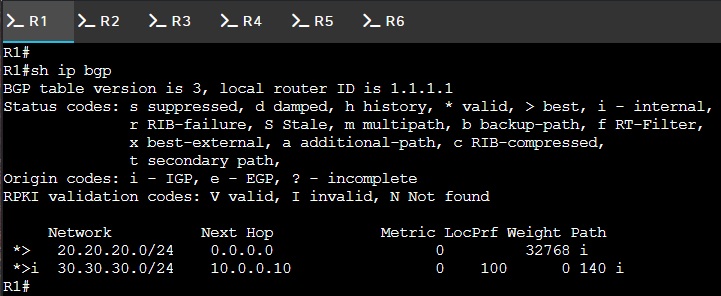
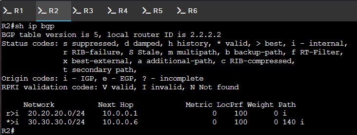
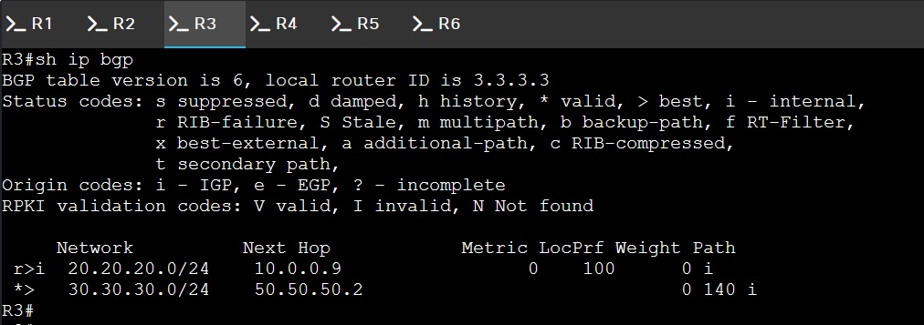
The output from show ip bgp is mirrored in AS-140. Each router in AS-100 can reach the
30.30.30.0/24 network (as well as the 2001:dead:2::/64 network), and each router in AS-140 can reach the
20.20.20.0/24 network (as well as the 2001:dead:1::/64 network).
There’s just one small problem.
What in the HELL is THIS?


This might have been an example of how helpful it is to run two layer-3 protocols, except I’m getting
the exact same error when I run the IPv6 equivalent of show ip bgp, which is the always easy
to remember show bgp ipv6 unicast command:
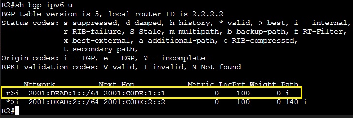
Nuh Uh YOU’RE the Rib Failure!
So. At this stage it feels appropriate to confess that I became arguably obsessed with these little
buggers (the “r” notation) that kept appearing in the output of my
show ip bgp / show bgp ipv6 unicast commands. It didn’t appear that they
were bothering anything. Except me. They bothered me very much. My thought-process went something like
“hey buddy, so you know you can’t present any of this shit unless/until you can explain what
the hell those damn things are, why it’s there, and how to get rid of them, RIGHT?”
As it effects us (network engineers), this is the most pertinent piece to grab hold of: (from Cisco’s BGP RIB Failure doc)

This is going to happen anytime your IGP is advertising a route that BGP is also advertising. In my case, R2 and R3 learned about the 20.20.20.0/24 route from R1 via OSPF. Then those routers RE-learned that route via BGP (at R1 we have a “network” command). OSPF has an admin distance of 110, but really any IGP is going to beat the hell out of BGP’s admin distance of 200. Therefore, when BGP loses this fight (which it always will!), it gets mad and sticks an “r” in front of that route. R1 and R6 don’t have it, because they’re directly connected to the BGP-promoted networks, but all the other routers have this for their local network because BGP lost a fight.
I literally spun up two identical versions of this lab to test this, but really all you need to do is remove the ospfv3 configurations from GigabitEthernet0/2 on R1 (the equivalent of removing the OSPF network command for that route) and those go away.
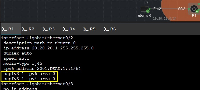
(you can remove these by prepending “NO!”)
With OSPF removed for both IPv4 and IPv6 on the G0/2 interface, the other routers don’t learn about the 20.20.20.0/24 route—except from BGP, where we have network commands issued for both that route and the 2001:dead:1::/64 route. And now that BGP’s foe has conceded, it removes the “r” from our BGP tables:
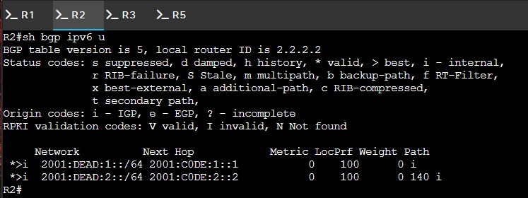
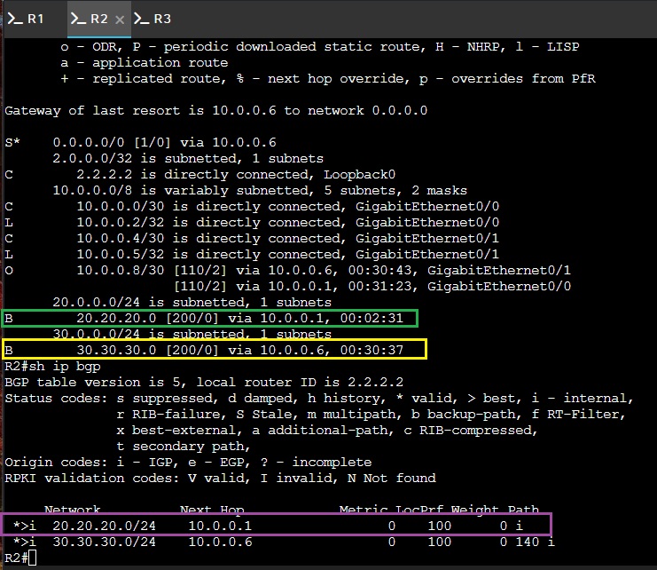
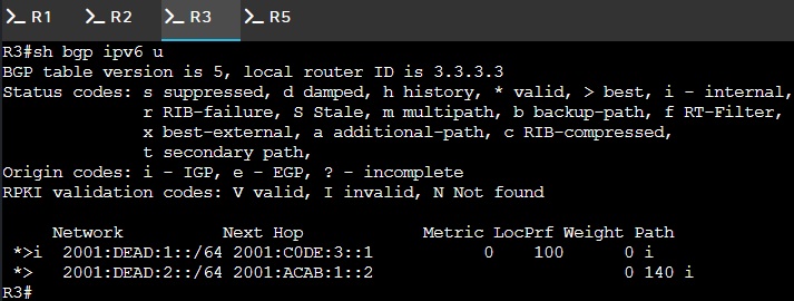
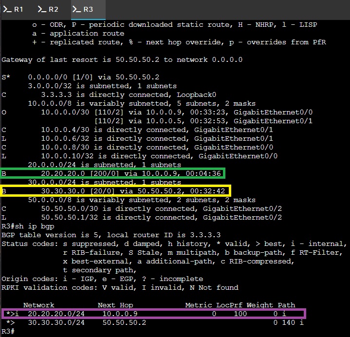
So, after going through all that work...I’m not actually convinced I gained anything here. I guess I have “one source of truth” for my shared routes, but what if I want my IGP to run routing within my AS? I haven’t read anything especially compelling that this needs to be done. hmu my email at 1234 Fake Street if you read this and have a compelling use-case you want to get off your chest. You may even be featured in network-foibles “BGP Part II” series!
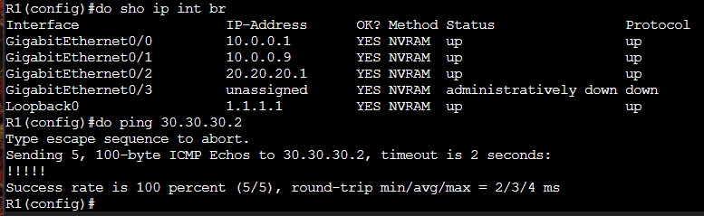
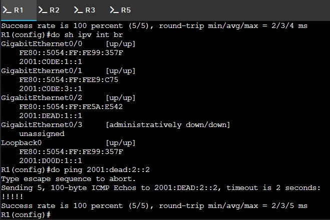
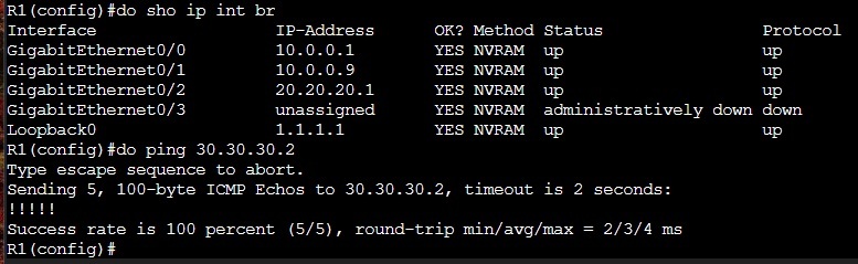
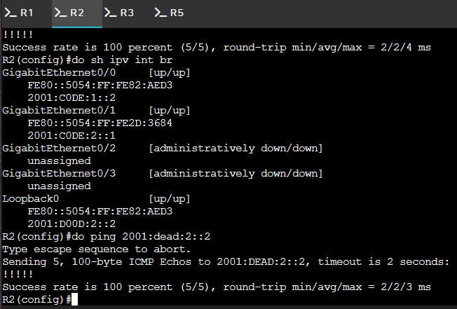
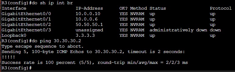
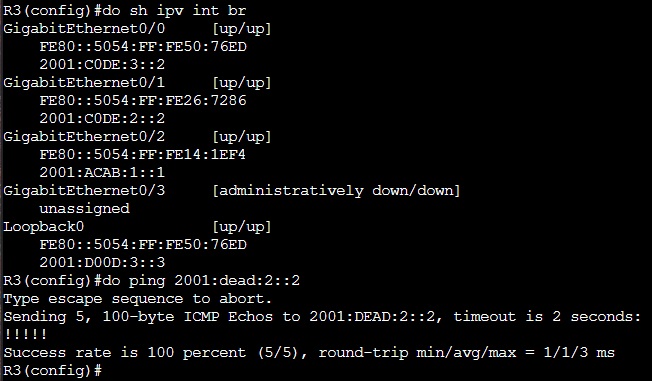
Alright, with or without OSPFv3 configured on that G0/2 interface, we have successful pings from our 3 routers:
Lab 3: BGP AS-Path Override, Route-Maps, and Advertisement Filters, Oh My!
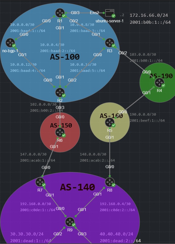
This was one of those “oh shit maybe I don’t know anything about networking”-types of labs to build, but the concept is fairly straightforward: AS-100 has a user network located off router R1 (using 172.16.66.0/24 and 2001:b0b:1::/64) that’s accessing remote networks 30.30.30.0/24 (a.k.a 2001:dead:1::/64) and 40.40.40.0/24 (a.k.a. 2001:dead:2::/64) in AS-140. By default, users will take the shorter AS-path through the R2 edge to AS-150 to reach these remote networks within AS-140. What we want to do is implement a policy change for the 30.30.30.0/24 and 2001:dead:1::/64 networks where our users take the longer AS-path out of R3 to AS-190, 160, then AS-140, while keeping the default path for the other 40.40.40.0/24 and 2001:dead:2::/64 networks. Once the default conditions are achieved (remote reachability), we can implement this policy change with the BGP configuration we deploy from AS-100 without having to change the configuration of any other routers on the topology. Luckily, I’ve seen a few youtube videos on the BGP Best Path algorithm so this should be a breeze.

Honestly, the hardest part of this lab was setting up the default conditions correctly. I’m testing
(read: pinging/tracerouting) from R1’s G0/3 interface, as an end-user in the 172.16.66.0/24 network.
Since I’m not using the BGP network command on that address block (it’s an
unrouteable 1918), how is my ping going to get back to me? I’ll save you the rending of garments
I did and simply state that you must take the block of public addresses assigned by your ISP and assign it
a static route to the null0 interface of your edge router, assign that same block to an NAT pool, then
advertise that network with the BGP network command. Literally everyone knows this except for
you:
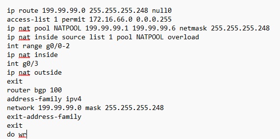
Here is a more credible source with a brief explanation: Cisco Community — NAT pool route to null0
Oh and since I’m not advertising 172.16.66.0/24 within BGP, I can advertise it on OSPF without BGP getting all jealous and putting RIB-Failure on all my BGP tables.
Anywhoozle, the base-configuration of everyone in the topology is included here (this is everything minus NAT and BGP):
Click router or server for base config commands
BGP Configuration
Our BGP configuration at this stage is pretty standard fare. On the left side of AS-100 I have a router called “no-bgp-1”, which receives no BGP configuration whatsoever (I had an idea for this router, but that was months ago and now it just hangs out in my topologies like a vestigial organ). I have an internal router, R1, which hosts my private user network at 172.16.66.0/24. This router uses BGP to get news about the outside world, but it doesn’t host anything public, so its configuration is just its peering relationship with the other BGP routers. I have two edge routers, and those will each get next-hop-self for their iBGP peers in their IPv4 and IPv6 BGP implementations (including to each other). On the opposing side, R7 and R8 both have next-hop-self for each other and R9, while R9 has 4 BGP network commands issued for the two IPv4 and two IPv6 networks it’s sharing.
Click router for BGP config commands
So in this scenario, I have dedicated public /29 networks for both of my edge routers. R2 has 199.99.99.0/29 and R3 has 199.99.99.8/29. That makes .16 the next network, meaning .15 is a broadcast and thus R3’s NAT pool goes from .9 - .14.
Click edge router for NAT and BGP edge config
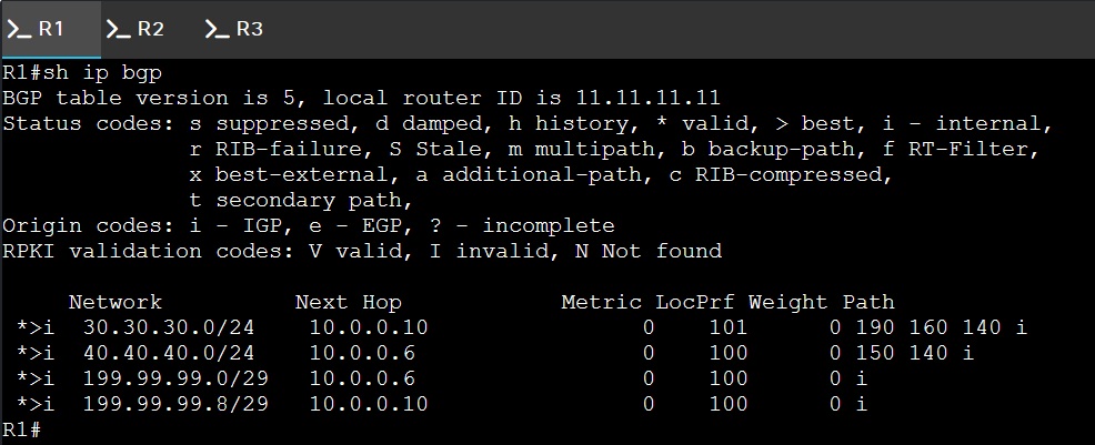
At the end of all of this, R1’s BGP table should look like this:
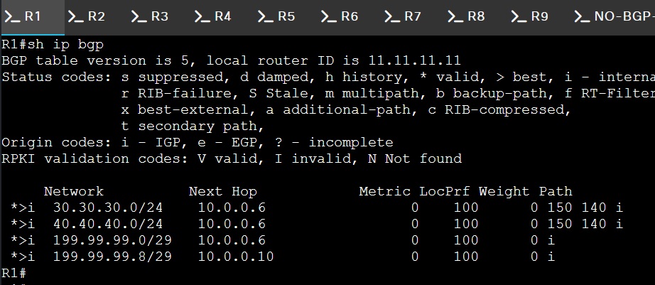
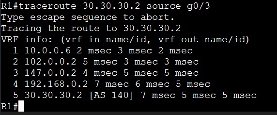
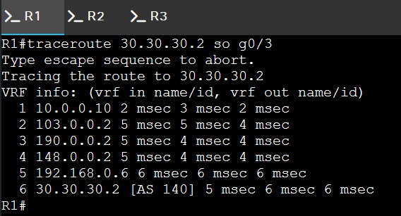
And R1’s traceroute output should look like this:
Route Maps & Route Advertisements Filters
It’s official: we’ve achieved our default condition! User traffic as predicted is taking the shorter AS-path through AS-150. From this point, there are a number of different labs you can construct where you’re using the BGP Best Path algorithm and your knowledge of how its attributes work to perform traffic manipulation. There are a number of ways to do this!
My way in this instance, which may not be the best way, is to do this the sneaky way and assign a “Local Preference” to R3 of 101, using a route-map tied to the 30.30.30.0/24 network specifically. To be clear, you can assign local-preference directly to your BGP configuration, like this…
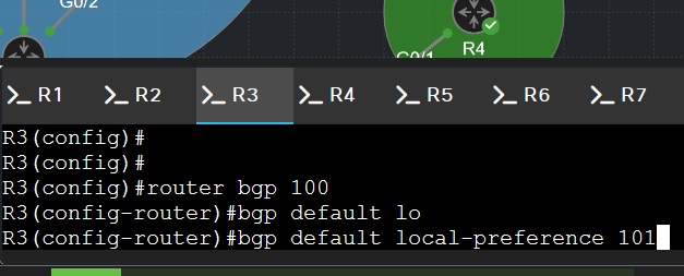
…but that will give R3 priority to ANY route learned by either R2 or R3. No, we use route-maps for this so we can tie it to a specific network.
You may ask: Mihkel, why is this “sneaky”? Good question! As the name portends, “local preference” is a local attribute; its value is meaningless outside of AS-100 as it doesn’t traverse eBGP peerings. Thus it’s sneaky because the cause of the change in traffic behavior is invisible to anyone outside AS-100!
Here’s how you actually assign the route-map:
Click router for route-map configuration
There’s just one problem.
Do you remember how I said nobody outside AS-100 ever heard of your local preference?
When I initially hatched my sneaky, clever plan, my thinking was I could control what path the packets take back because they’ll be tied to R3’s public addresses via NAT. I hadn’t accounted for the fact that R2 would ALSO advertise R3’s 199.99.99.8/29 network because duh why wouldn’t it!? It learned that network from its good buddy R3 via iBGP! So now R7 and R8 both know they can skip the line and take the shorter AS-path through AS-150, thus breaking NAT (return traffic won’t be in R2’s NAT translation table and will get dropped like an egg from a tall chicken).
The solution is to put advertising filters on R2 and R3 edges so they’re not advertising each other’s public routes.
This is how you implement address-filtering at the edge:
Click edge router for advertisement filter configuration
Important implementation note: You can’t have two route-maps on the same neighbor’s ingress/egress. If you look carefully, R3 has two route maps applied to the same neighbor, but the local-preference assignment applies to ingress traffic (denoted by the “in” at the end of the neighbor statement) whereas the advertisement filter is assigned as an egress rule (denoted with “out”).
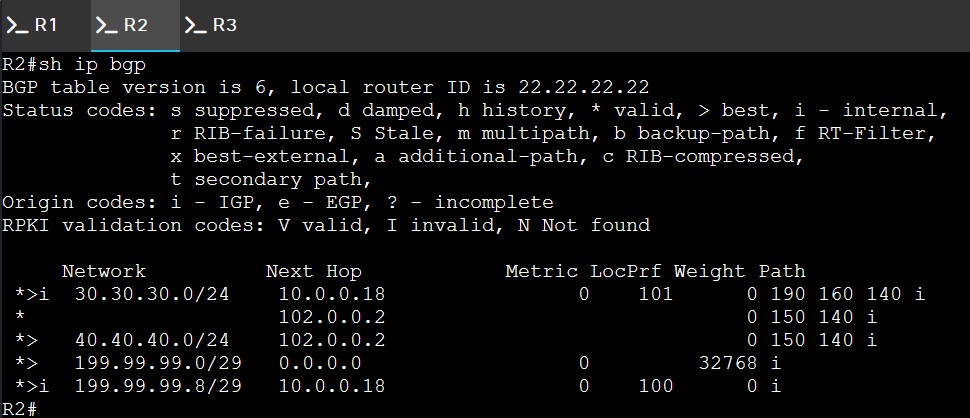
Non-networking people will never know what this FEELS like:
github.com/mihkel-bonafide — profile with lab repos, configs, and automation experiments.